Ac To Dc Converter Using Matlab Simulink
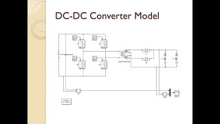
DC to DC Buck Converter simulation with MATLAB Simulink Model. The 600V 60 Hz voltage obtained at the secondary of the WyeDelta transformer is first rectified by a six pulse diode bridge.
![]()
Matlab Model Of 72 Pulse Ac Dc Converter Fed Dtcimd Zero Sequence Download Scientific Diagram
A 60 Hz voltage source feeds a 50 Hz 50 kW load through an AC-DC-AC converter.
Ac to dc converter using matlab simulink. Ac to dc converter simulink. AC to DC Converter MATLAB Simulink Simulation Complete TutorialAC to DC Converter MATLAB Simulink Simulation Power ElectronicsAC to DC Converter using Thyris. The switches mainly used are the Core switches of Power Electronics.
The IGBT inverter uses Pulse Width Modulation PWM at a 2 kHz carrier frequency. 4 Simulation Closed-Loop of DC-DC Converters Using Cascaded Control The simulation model for cascaded control of DC-DC switching converters is build using the above-mentioned steps is as shown in Fig. Run the simulation and observe waveforms on Scope.
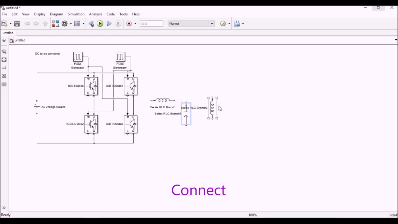
In the explanation below we will design a three phase inverter in Simulink. The switches mainly used are the Core switches of Power Electronics. Dc to dc buck converter is a converter in which dc voltages are step down to desired level by high frequency switching of semiconductor switches such as MOSFET or IGBTs.
The circuit is discretized at. Boost converter simulationmodelling using simulink MATLAB. Vout 24 1 - 05 48 V.
The 600V 60 Hz voltage obtained at the secondary of the WyeDelta transformer is first rectified by a six pulse diode bridge. MathWorks engineers show how to use Simulink and Simscape Electrical to develop simulate and implement a controller that maintains desired output voltage in the presence of input voltage variations and load changes to achieve a fast and stable response. The IGBT inverter uses Pulse Width Modulation PWM at a 2 kHz carrier frequency.
Alternatively a three phase inverter uses two input DC sources using 6 IGBT transistors to convert DC voltage into AC voltage and the output of such a circuit will be a three phase AC waveform with a phase difference of 120. This type of converter is also called step down converter. The filtered DC voltage is applied to an IGBT two-level inverter generating 50 Hz.
The circuit is discretized at. A 60 Hz voltage source feeds a 50 Hz 50 kW load through an AC-DC-AC converter. In the circuit a bridge like circuit comprised of IGBT transistor is used which converts DC to AC.
The filtered DC voltage is applied to an IGBT two-level inverter generating 50 Hz. Verify that the mean value of the load voltage Vout is very close to the theoretical value of. A boost converter step-up converter is a DC-to-DC power converter with an output voltage greate.
This video explains about the design and simulation of dc dc converter in boost mode with open loop controls using matlab simulink diamond matlab tutorials. Ac to dc converter matlab simulink simulation complete tutorial duration. The circuit is discretized at.
If we talk about regulated supply then it is not so much difficult in ac side but in dc side it is so. See how to use. The IGBT inverter uses Pulse Width Modulation PWM at a 2 kHz carrier frequency.
The filtered DC voltage is applied to an IGBT two-level inverter generating 50 Hz. In this example the converter is feeding an RC load from a 24 V source and the PWM frequency is set to 20 kHz. This video explains about the design and simulation of dc dc converter in boost mode with open loop controls using matlab simulink diamond matlab tutorials.
Ac to ac converters. Use the simulation model to size passive components calculate power losses design digital pid controller and implement it on ti tms320f28035. In this simulation we can use bidirectional switches to and convert AC into DC respectively.
Get a demonstration of SEPIC circuit topology and how to model and simulate a DC-DC converter that powers a strip of LEDs. 10The DC-DC buck boost buck-boost and Cuk converters was previously designed and simulated on digital computer using Matlab package with. Get the code from herehttpsgumcoMcYtFAn ACDC con.
I want ACDC converter using simulink. The 600V 60 Hz voltage obtained at the secondary of the WyeDelta transformer is first rectified by a six pulse diode bridge. Single phase AC to DC converter by Matlab Simulink by Andhra university students Visakhapatnam.
About Press Copyright Contact us Creators Advertise Developers Terms Privacy Policy Safety How YouTube works Test. A 60 Hz voltage source feeds a 50 Hz 50 kW load through an AC-DC-AC converter. If we talk about regulated supply then it is not so much difficult in ac side but in dc side it is so much difficult and this is only possible with.
Matlab simulation of single. Learn how to model and simulate a DC-DC converter in Simulink and Simscape Electrical. Matlab simulation of buck boost converter with closed loop control duration.
Learn more about simulink converter acdc power_electronics_control power_conversion_control.

Three Phase 3 Q Ac To Dc Converter Using Thyristor By Matlab Simulation Youtube

Ac Dc Three Level Pwm Converter Matlab Simulink
Simulation Of Dc Dc Converter Using Matlab Simulink Simulation Of Dc Dc Step Up Converter Youtube

Ac To Dc Converter Matlab Simulink Simulation Complete Tutorial Youtube
Dc To Ac Converter Simulation Youtube
How To Make Bi Directional Ac To Dc Power Converter On Matlab Simulink For A Microgrid Model Quora

Ac Dc Ac Converter Matlab Simulink

Dc Dc Converter Circuitry Model File Exchange Matlab Central

Three Phase Ac Dc Ac Pwm Converter File Exchange Matlab Central

Ac To Dc Converter In Matlab Simulink Youtube

Closed Loop Simulink Model Of Three Phase Ac To Dc Boost Converter With Download Scientific Diagram

Buck Boost Converter Matlab Simulink

Matlab Simulink Sim Power Systems Model For A Pwm Ac To Dc Converter With Line Conditioning Capabilities Semantic Scholar

Buck Converter Matlab Simulink Mathworks Switzerland

Closed Loop Simulink Model Of Three Phase Ac To Dc Boost Converter With Download Scientific Diagram

Push Pull Dc To Ac Converter File Exchange Matlab Central
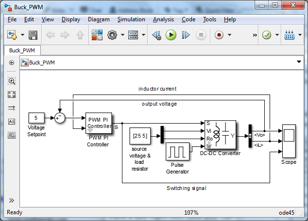
Configurable Simulink Model For Dc Dc Converters With Pwm Pi Control File Exchange Pick Of The Week Matlab Simulink

Converters Low Power Matlab Simulink
Simulink Diagram Of The Control Of The 3 Phase Ac Dc Converter Download Scientific Diagram
Post a Comment for "Ac To Dc Converter Using Matlab Simulink"